HYDROMINE™ LFC_3B Flow Control Valve System (For Semi Closed Loop Cooling System)
OVERVIEW
The HYDROMINE™ LFC_3B flow control valve system was developed to control flow over mobile or bulk air-cooling coils in a typical mine water reticulation cooling system and turn it into a semi closed loop cooling system. The systems are developed to maintain a designed flow over the coil and feed the warm water back to the mining production line, irrespective of any changes in upstream pressure or demand of flow changes in the piping system. Once the flow demand for mining production decreases below the designed flow of the coil, the system starts returning water in a return line back to the fridge plant.
This system minimises water usage, reduces water cooling wastage and keeps the coil energy efficient. Coils can be added or removed in the piping system as required and HYDROMINE™ LFC_3B flow control valve system will adjust according to the demand changes. When there are no flow control valve systems installed, all the flow through the coil will be returned to the fridge plant or dumped on the foot wall, wasting excessive water and energy. Further the flow in the coil will increase when the upstream pressure rises. When the upstream pressure drops, the flow will decrease. Both these scenarios will cause the coils to operate insufficiently.
With the HYDROMINE™ LFC_3B flow control systems, the water will be returned to the mining production pipe line and while there is a flow demand, flow will remain constant and the coils will operate at their designed flow rate, making this system very efficient.
The HYDROMINE™ LFC_3B flow control valve system has been developed to present a robust, simple and cost-effective solution to fluid handling issues in the mining sector (up to 2.5 MPa / 363 psi).
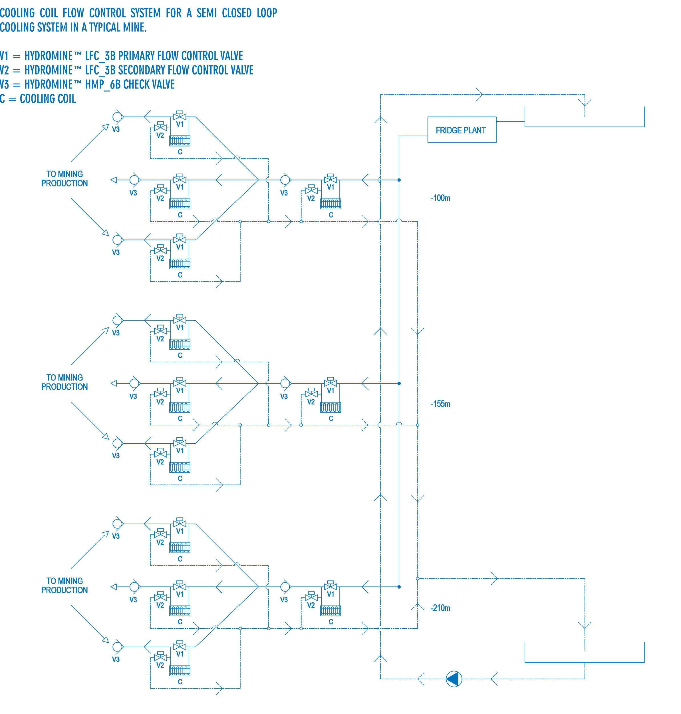
COOLING COIL - FLOW CONTROL SYSTEM FOR A SEMI CLOSED LOOP COOLING SYSTEM IN A TYPICAL MINE
OPERATING CONDITIONS
These HYDROMINE™ LFC_3B valve systems are developed to operate in systems with relatively clean media such as water or other liquids with a low percentage of suspended solids and chlorides. The valve's operating pH range is 2 -14 pH.
SIMPLICITY
The HYDROMINE™ LFC_3B flow control valves are designed to minimize wearing parts and in essence, only has one moving part called the plug assembly. The plug assembly is a piston that is engineered to be unbalanced. The unbalanced plug is designed to use inline fluid pressure to create specific conditions in the system without the use of an external controller or pilot. A fixed reduction ratio can be established by fixing the surface area ratio exposed to the upstream and downstream differential pressures (dP).
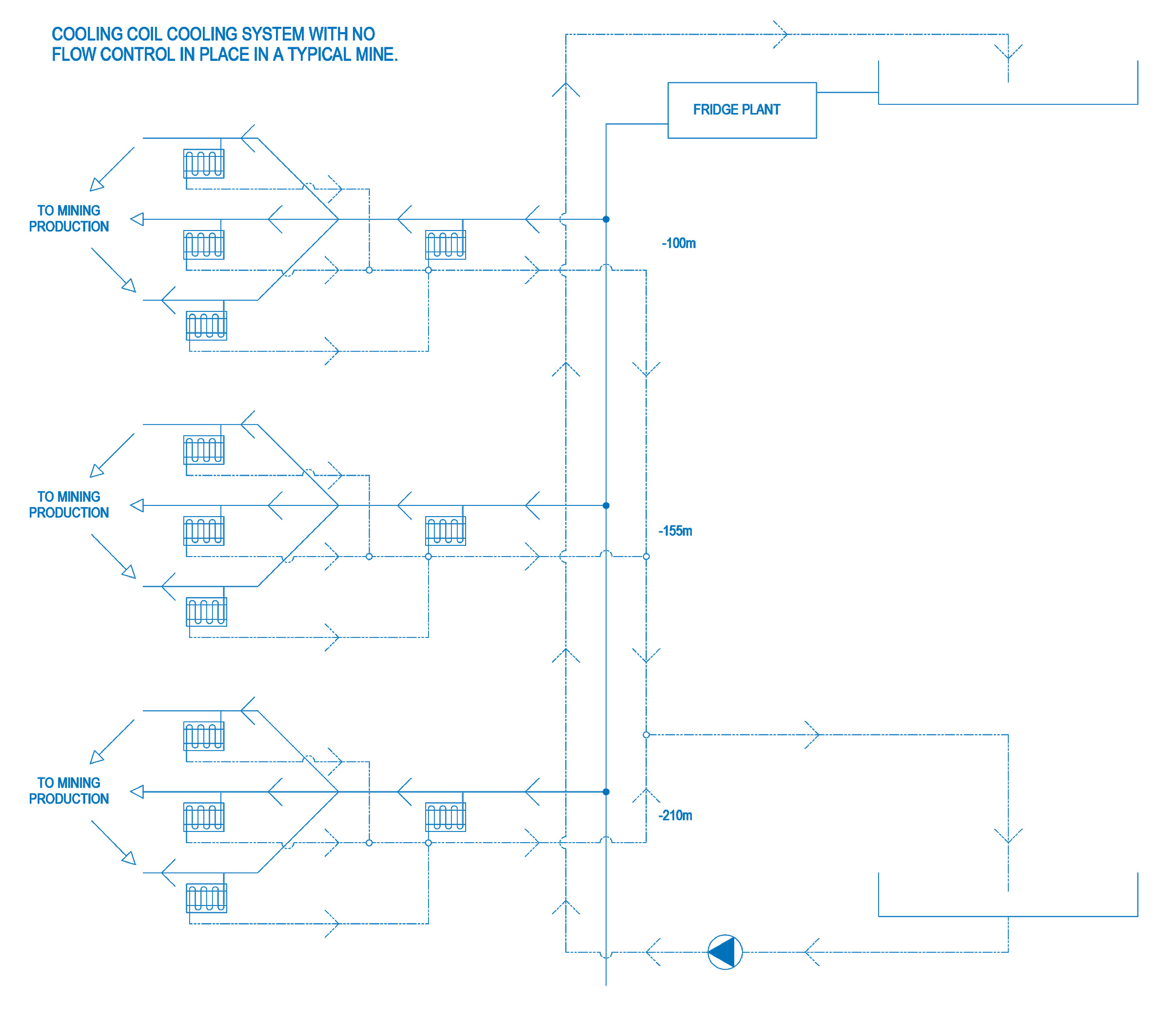
TYPICAL COOLING SYSTEM INSTALLATION IN AN UNDERGROUND MINE WITH NO FLOW CONTROL SYSTEMS IN PLACE
In the diagram below, it shows a typical mining cooling system with no flow control systems installed. The diagram clearly demonstrates how all the flow through the cooling coils is returned to the fridge plant. This system is not energy efficient as all the water is returned to the fridge plant and not re-used for mining operations.
Some of the older mines do not even have a return line system in place and dumps all the flow through the cooling coil on the foot wall. A system like this is inefficient as all the water must be cleaned, chemically treated and pumped away, increasing the mine’s operating cost.
TYPICAL SEMI CLOSED LOOP COOLING SYSTEM INSTALLATION IN AN UNDERGROUND MINE
In the diagram below, it shows a typical mining semi closed loop cooling system with the HYDROMINE™ LFC_3B flow control systems installed. The diagram clearly demonstrates how the system became more energy efficient, as the water flow through the cooling coils is returned to the mining operations, decreasing water usage. Only once the mining operations use less flow than the coils design flow, or no flow, water is returned to the fridge plant. A system like this decreases the mine’s operation cost and makes the mine more energy efficient.
MAINTENANCE REQUIREMENTS
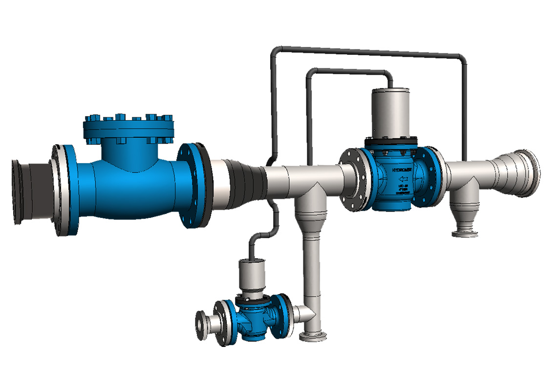
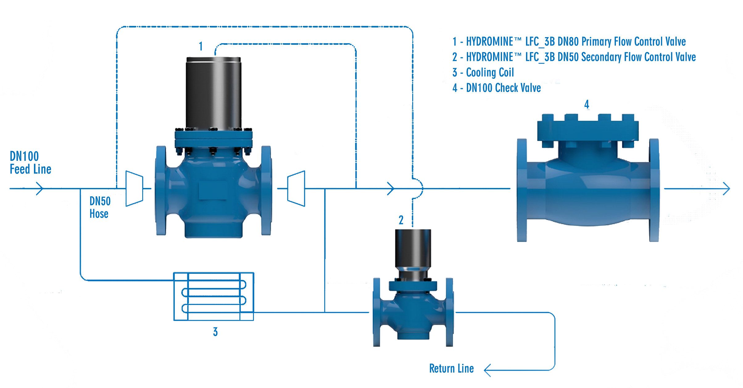
The HYDROMINE™ LFC_3B flow control system is equipped with a HYDROMINE™ LFC_3B Primary flow control valve, HYDROMINE™ LFC_3B Secondary flow control valve and HYDROMINE™ HMP_6A Check valve. It is recommended that a maintenance schedule is established to clean reverse flush the coil, wash the coil, and service both the HYDROMINE™ LFC_3B flow control valves. All the moving parts of the HYDROMINE™ LFC_3B flow control valve are manufactured from stainless steel which increases reliability and durability. The HYDROMINE™ LFC_3B requires minimal maintenance, the majority of which, can be conducted with the valve remaining in situ.
PRESSURE MEASURING POINTS AND RISK ASSESSMENT
The HYDROMINE™ LFC_3B flow control system is designed and manufactured for easy installation with less risk of making mistakes.
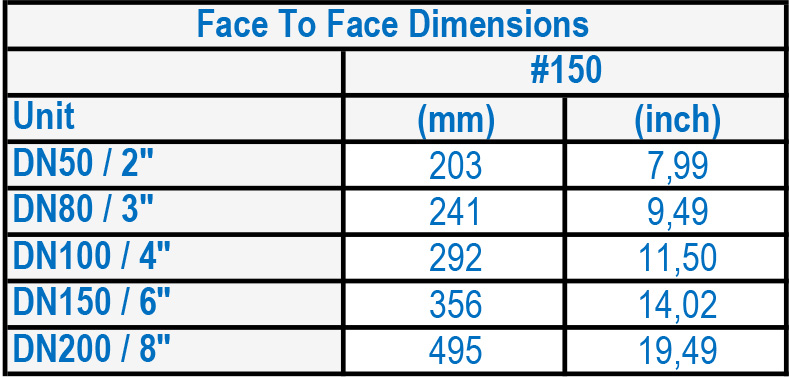
DIMENSIONS OF HYDROMINE™ LFC_3B FLOW CONTROL VALVE
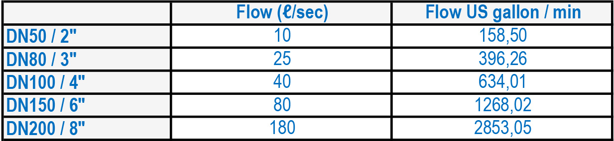
MAXIMUM FLOW RATES
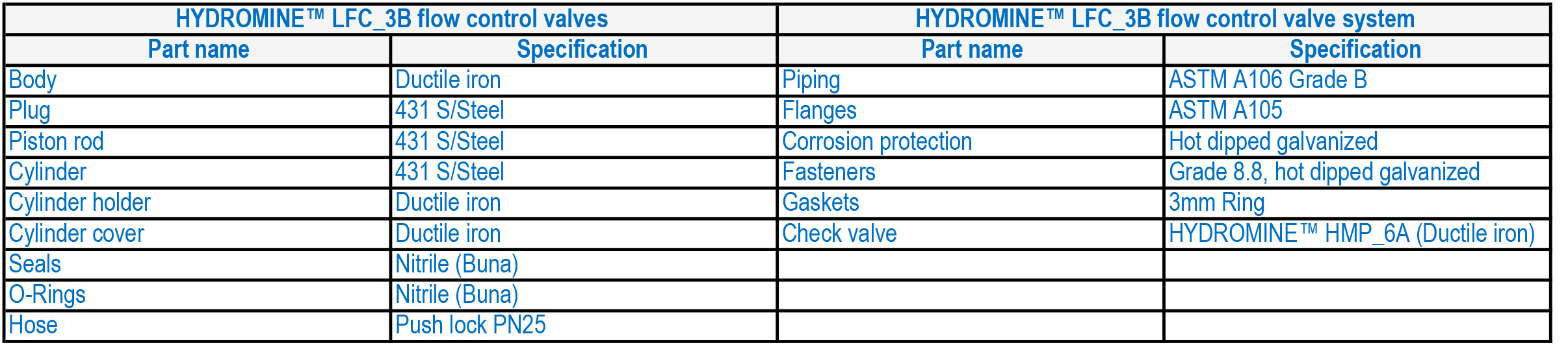
MATERIALS OF CONSTRUCTION
DESIGN AND MANUFACTURING STANDARDS
The HYDROMINE™ LFC_3B flow control system has been designed in accordance with various international standards as set out below: ASME Boilers and pressure vessels design code.
ASME Boilers and pressure vessels design code.
ANSI B16.10 API 598
ANSI B16.34 ANSI B16.37
ANSI B16.5 ANSI N278.1
Available sizes: DN50 / 2" to DN400 / 16"
Pressure rating: up to 2.5MPa / 363 psi
Face to face dimensions: ANSI B16.10
Available end connections: ANSI B16.5, BS4504, BS10, AS/NZS 4331.1 (ISO 7005-1) DIN, all makes of grooved or ring joint couplings, and other as per clients requirement.
DOWNLOADS