HYDROMINE™LFC_1B Surge Prevention Valve
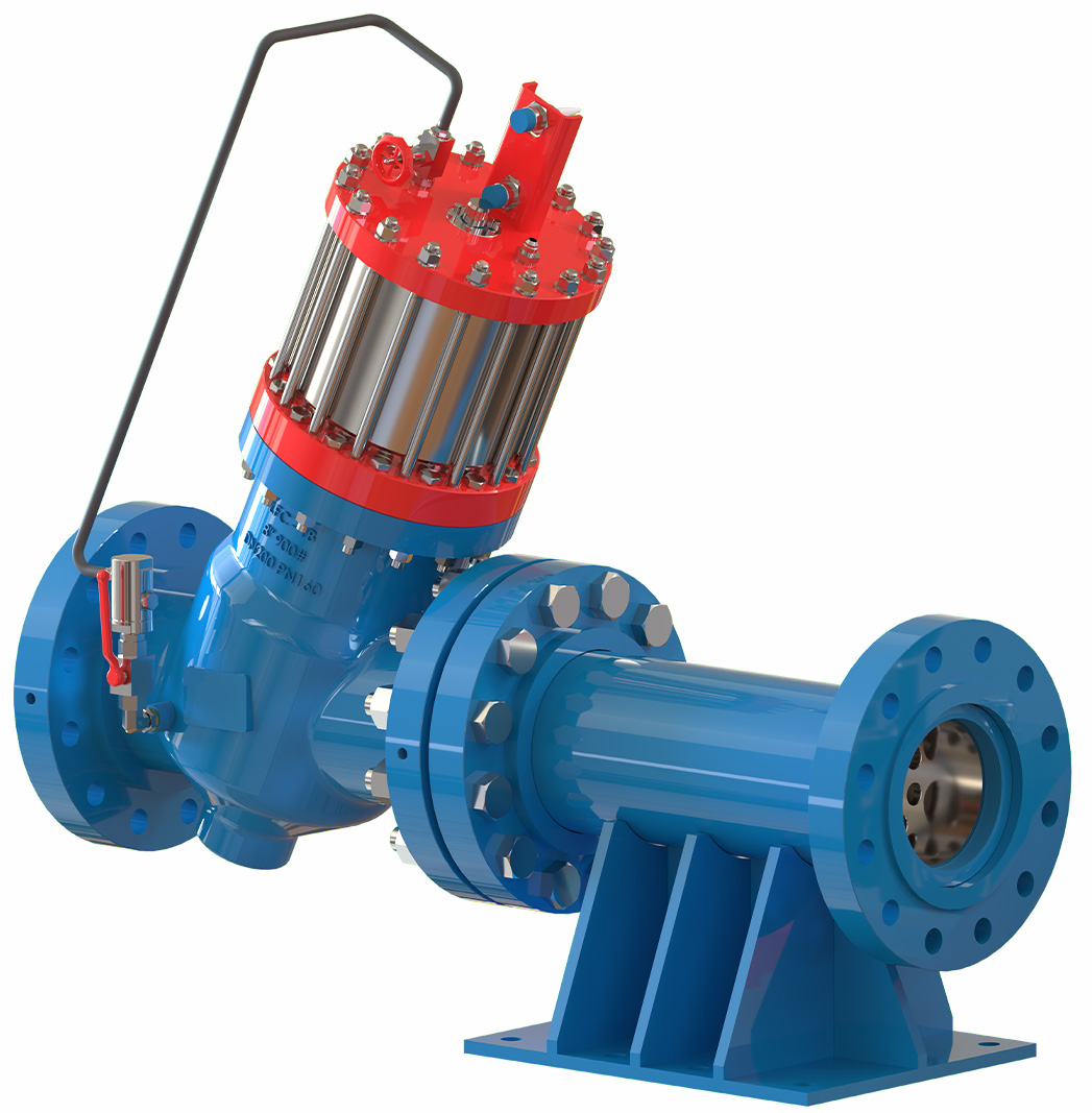 OVERVIEW
The HYDROMINE™ LFC_1B Surge prevention system is designed to prevent water hammer or pressure surges in pumping systems. Especially in deep mining applications where water hammer is more severe due to the vertical columns. Water hammer (or, more generally, fluid hammer) is a pressure surge or wave resulting when a fluid in motion is forced to stop or change direction suddenly (Momentum Change).
Water hammer commonly occurs when a pump is stopped suddenly and a pressure wave propagates in the pipe. It is a force that can arise in any pumping system that undergoes abrupt changes in its rate of flow. These flow changes can result from pump starts and stops, the opening and closing of valves, and water column separation and closure. The piping design does have an effect upon water hammer but, we have identified the main conditions resulting in hammer.
WHEN DOES WATER HAMMER / PRESSURE SURGE OCCUR?
Water hammer will normally occur in a pumping system when one of 3 conditions occur:
1. A total power failure, causing all the running pumps to trip.
2. The emergency stop is activated on the last running pump.
3. Tripping of the last running pump.
WATER HAMMER / PRESSURE SURGE
Typically, water hammer travels at the speed of sound through it's medium which can amount to 1 481 m/s (Ave 995m/s) in water. Water is only partially compressible. At ambient temperature one pound of pressure will decrease its volume by a factor of about 0.0000034. The larger the volume of water, the easier it is to see the effect of water hammer. Compression begins at the leading edge of the water column and when the additional energy it produces cannot continue past the closed valve (Check / Non-Return), a pressure or shock wave is generated which travels back upstream. The inception of this shock wave is very similar to the "echo" that is produced when a sound wave, traveling through air, strikes some barrier. When the wave hits the upstream valve, it is reflected downstream but with a diminished intensity. This, back and forth, motion continues until friction and reflection losses cause the waves to dissipate. The speed at which a wave travels and the energy it loses during travel depends upon the density and compressibility of the medium in which it is traveling. It turns out that the density and compressibility of water make it a very good medium for shock wave generation and transmission.
SIMPLICITY
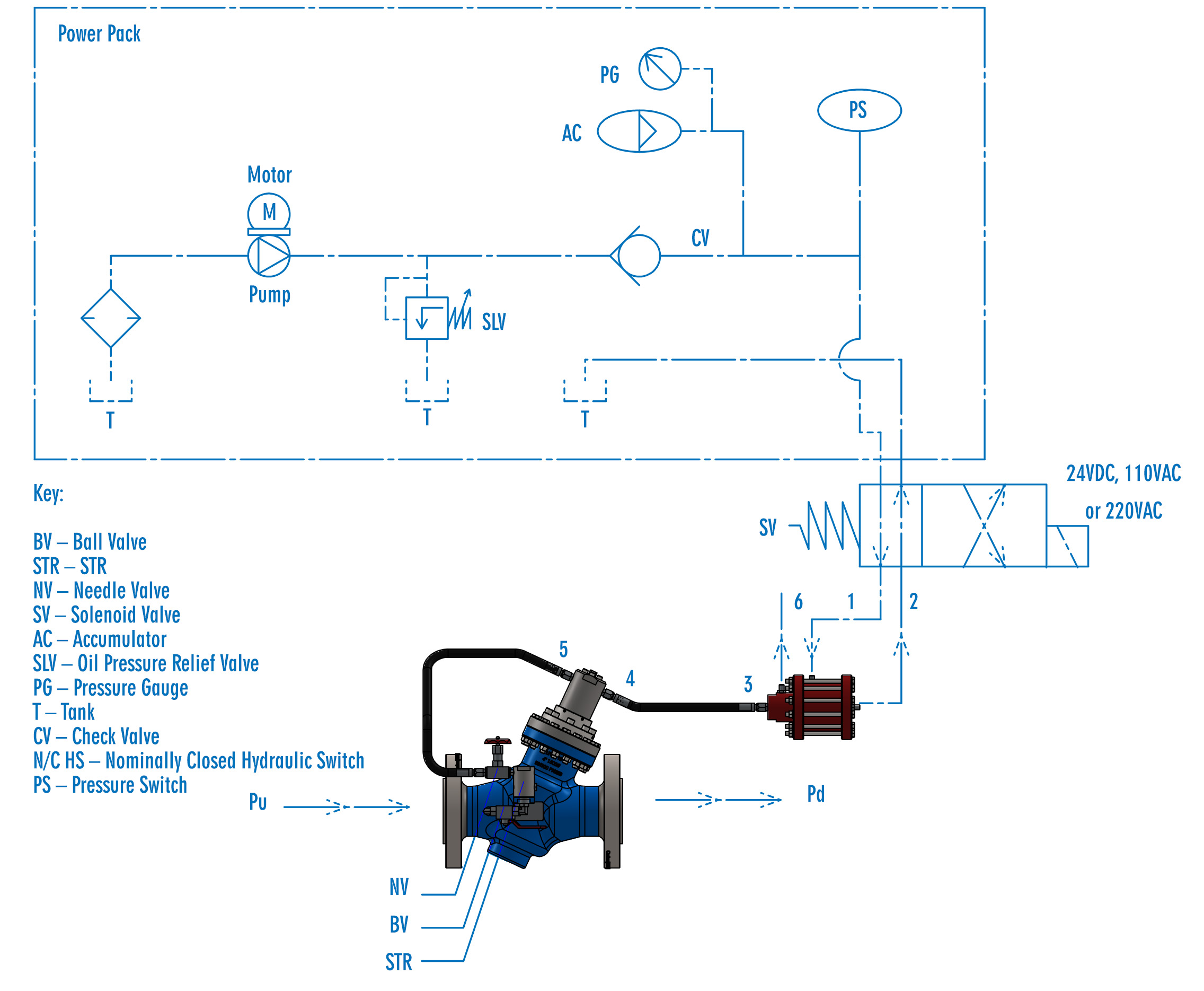
The HYDROMINE™ LFC_1B Surge prevention valve system is designed to minimize wearing parts and in effect only has one moving part called the plug assembly. The plug assembly is a piston that is engineered to be un-balanced. The HYDROMINE™ LFC_1B Surge prevention valve is water hydraulically actuated using a hydraulic switch. The function of the hydraulic switch is to displace water from the control chamber of the valve rapidly.
This rapid displacement of water causes the surge prevention valve to open extremely quickly. The hydraulic switch is controlled using a compact oil hydraulic power pack.
LOW MAINTENANCE REQUIREMENT
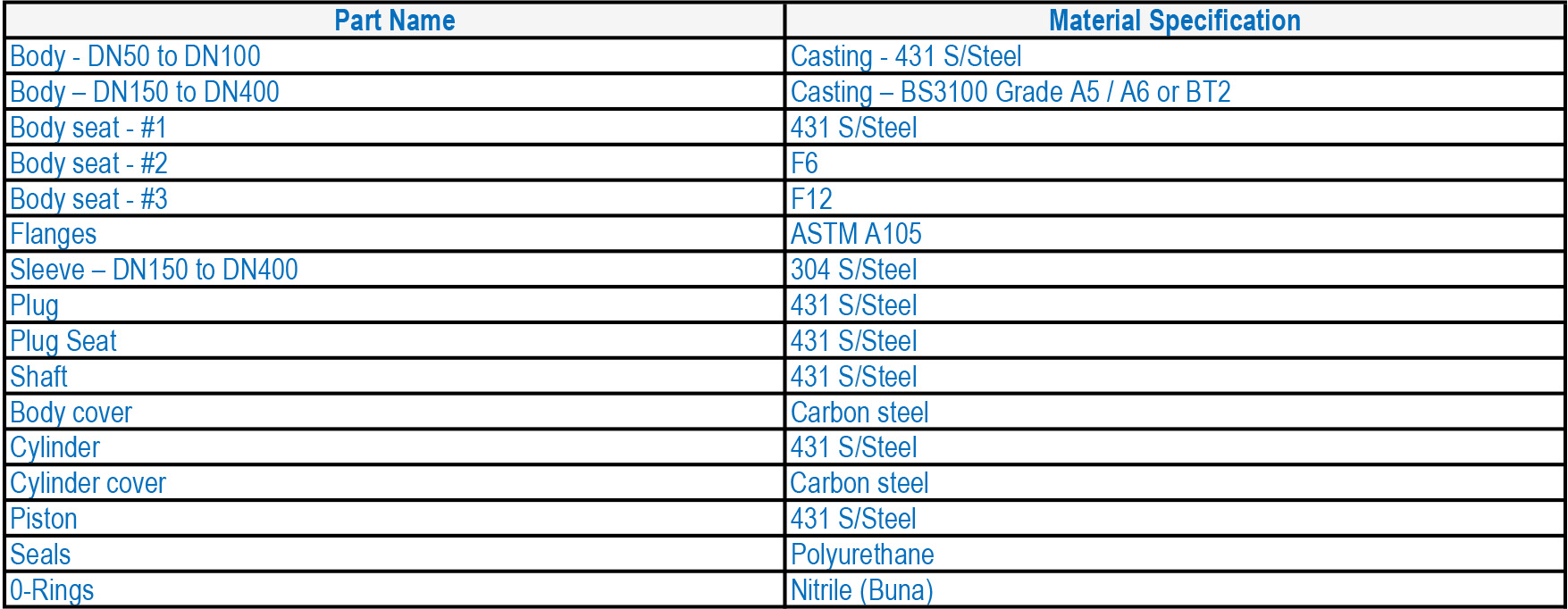
All the moving parts of the HYDROMINE™ LFC_ 1B Surge Prevention valves are manufactured from stainless steel which increases reliability and durability. The HYDROMINE™ LFC_1B valve range requires minimal maintenance, the majority of which, can be conducted with the valve remaining in situ.
OPERATING CONDITIONS
These valves are designed to operate in systems with relatively clean media like water or other liquids with a low percentage of suspended solids and chlorides. The valve's operating pH range is 2 - 14 pH.
THE EFFECTS OF WATER HAMMER / PRESSURE SURGE
The graph shows the effects of water hammer on a pump station in a Mine, with an underground pump station of 770m static head when 1 pump tripped.
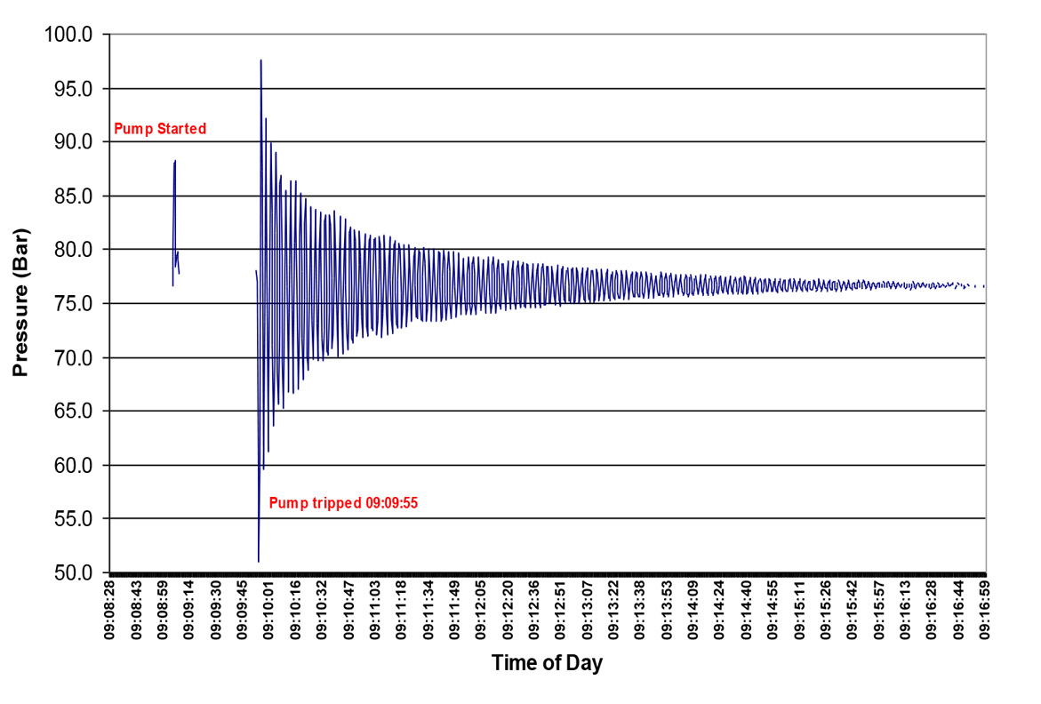
The graph shows the effects of water hammer in a Mine pump station, with an under ground pump station of 786m m static head when 2 pumps tripped.
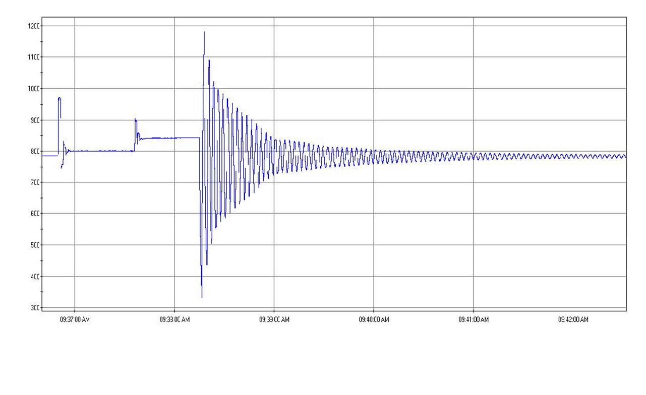
This is the result of water hammer in a Mine pump station, with an underground pump station of 750m static head after 1 pump tripped, due to a total power failure.
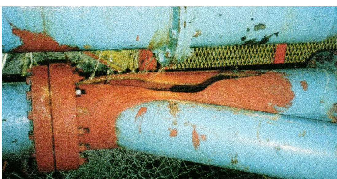
HOW DOES IT WORK?
The HYDROMINE™ LFC_1B Surge prevention valve opens rapidly when there is an abrupt stop of the last running pump, or a total power failure during dewatering. At that stage the flow is still moving away from the pump station, but as soon as it loses it's driving force and energy it will start returning towards the pump station. Due to the open HYDROMINE™ LFC_1B Surge prevention valve, the returning column of water is met with an open orifice and an exit point for any energy build up.
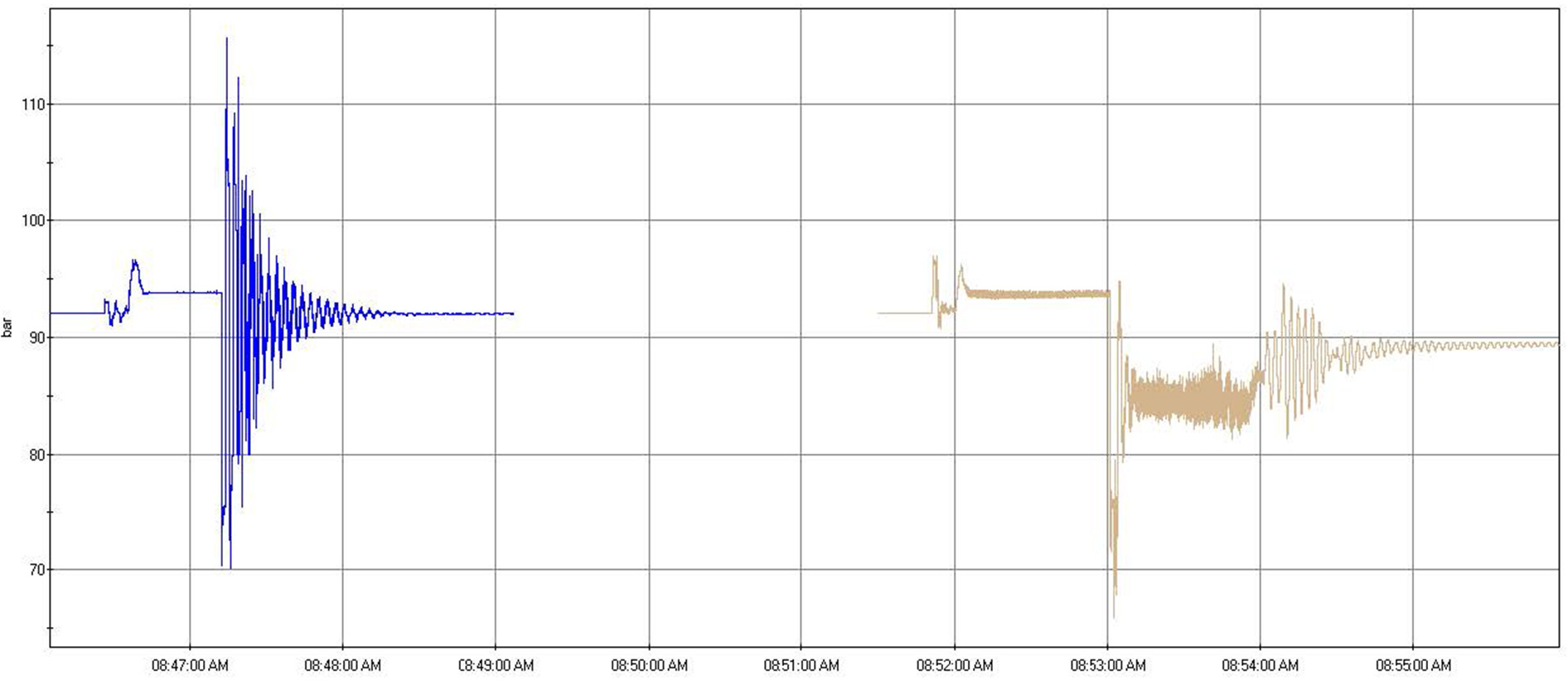
The flow moves through the HYDROMINE™ LFC_1B surge prevention valve and HYDROMINE™ LFC_7 energy dissipator installed after the valve. After keeping the HYDROMINE™ LFC_1B Surge prevention valve open for +/- 10 seconds, the surge prevention valve starts closing in a controlled manner to prevent any surging. The function of the energy dissipator is to discharge the flow at safe pressure and a set flow to atmosphere into the suction dam or drain. The graph on the left shows the effects of water hammer on an underground pump station with 920m static head when 1 pump tripped. The graph on the right shows the result of using the HYDROMINE™ LFC_1B surge prevention valve system in the same pump station, when 1 pump tripped. It clearly demonstrates the effectiveness of the solution and shows that no water hammer was experienced.
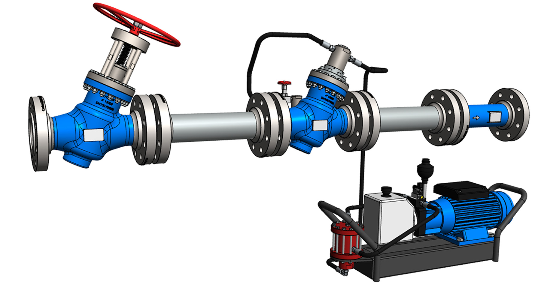
HYDROMINE™ LFC_1B SURGE PREVENTION SYSTEM WITH COMPACT OIL HYDRAULIC POWER PACK
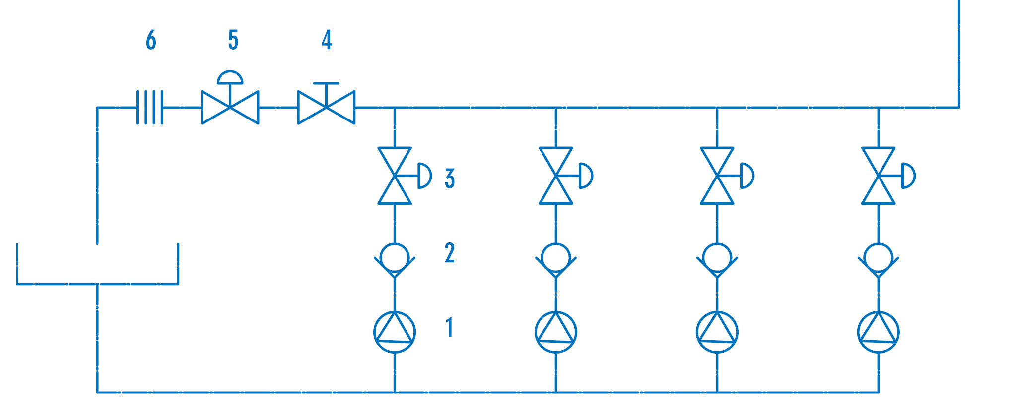
TYPICAL PUMP STATION WITH SURGE PREVENTION SYSTEM
SURGE PREVENTION SYSTEM
MATERIALS OF CONSTRUCTION
DIMENSIONS

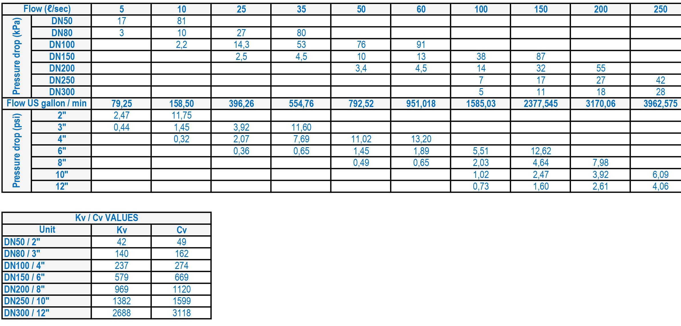
FLOW RATES
DESIGN STANDARDS
The HYDROMINE™ LFC_1B Surge Prevention valve has been designed in accordance with various international standards as set out below:
ASME Boilers and pressure vessels design code
ANSI B16.10
API598
ANSI B16.34
ANSI B16.37
ANSI B16.5
ANSI N278.1
Available sizes: DN50 / 2" to DN400 / 16"
Face to face dimensions to ANSI B16.10
Pressure rating: up to 25MPa / 3 626 psi
Available end connections: ANSI Bl6.5, BS4504, BSl 10, AS/NZS 4331.1 (ISO 7005-1) DIN, All makes of grooved or ring joint couplings, HYDROMINE™ HMP U-Coupling, HYDROMINE™ HMP™TE tapered couplings and other as per clients requirement.
DOWNLOADS


